
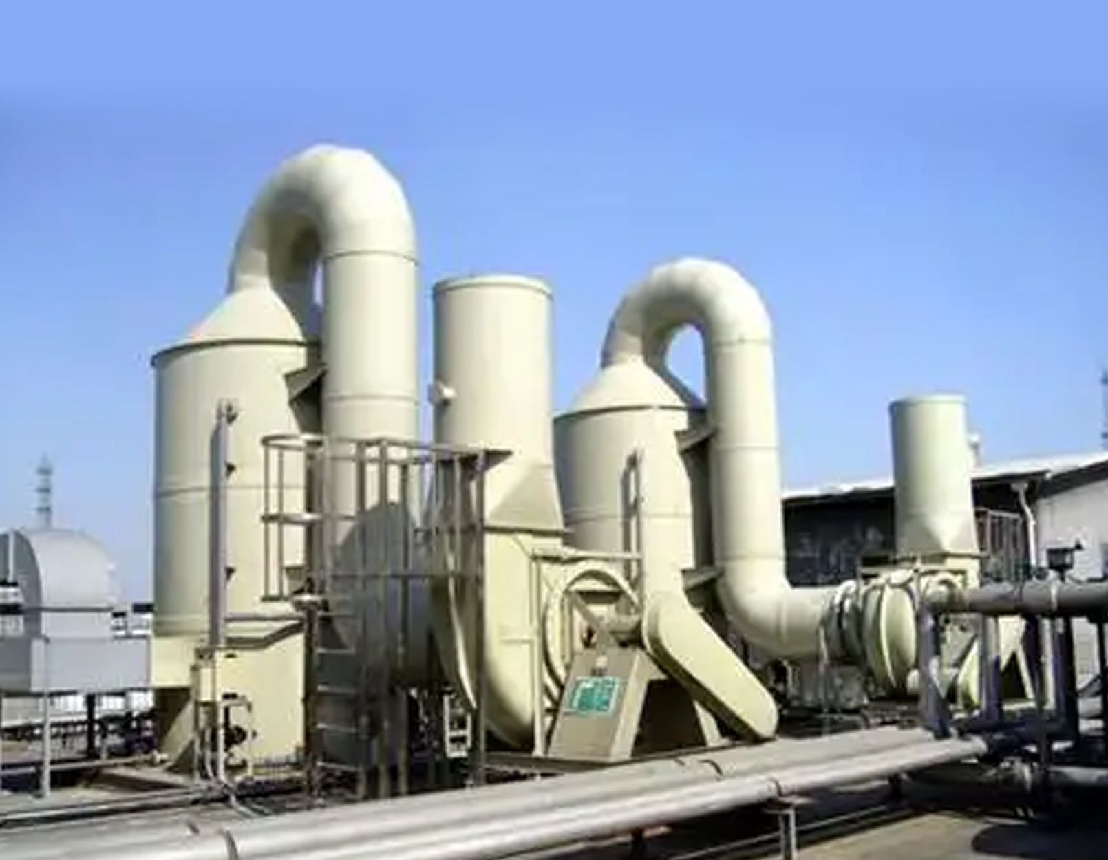
Components such as flue gas desulfurization (FGD) absorption towers, spray ducts, slurry circulation tanks, and flow-guiding structures are subjected to long-term gas-liquid-solid three-phase erosion conditions, where the flue gas—carrying fly ash, limestone crystals, and hard gypsum crystals—continuously impacts and abrades the lining. While perfluorinated fluoropolymers have become the mainstream choice for anti-corrosion linings due to their stable molecular structures, their inherent hardness is relatively low and their fatigue resistance is limited; consequently, continuous particle erosion leads to progressive, multi-type damage characterized by delamination.
Forms, Mechanisms, and Engineering Case Studies of Particulate Erosion Damage in Fluoropolymer Linings for Flue Gas Desulfurization (FGD) Units
I. Operating Conditions, Media, and Basic Properties of Lining Materials
1.1 Characteristics of Eroding Particles in FGD Systems
The eroding particles in desulfurization systems fall into two categories: fly ash carried in the gas phase (median particle size: 20–80 μm; Mohs hardness: 4–6; sharp, angular shape) and crystalline gypsum/limestone particles in the circulating liquid phase (median particle size: 50–200 μm; Mohs hardness: 3–5; hard, flaky crystals). Particle concentrations in localized eddy zones can reach 200–300 g/m³, and local fluid velocities in the spray zone range from 8 to 22 m/s; areas such as flow deflectors, tower corners, and locations directly beneath spray nozzles are hotspots for erosion.
1.2 Fundamental Mechanical Limitations of Perfluorinated Polymer Linings
The primary base materials for industrial desulfurization linings are three types of perfluorinated polymers: perfluoroalkoxy (PFA) resin, fluorinated ethylene propylene (FEP) copolymer, and polytetrafluoroethylene (PTFE). The Shore hardness of the pure base materials is only D50–D60; they exhibit high plasticity and poor resistance to micro-cutting. While nano-filler modification enhances wear resistance through mechanisms such as nano-phase pinning and crack bridging, it cannot entirely prevent the multi-stage damage caused by long-term, cyclic particle impact. Laboratory data indicate that under identical erosion conditions, the volumetric wear of unfilled, pure perfluorinated polymers is 4.2 to 6.8 times that of nano-silica-modified fluoropolymers; uniform dispersion of nano-fillers increases surface toughness by 45%, thereby inhibiting the propagation of early-stage micro-damage. II. Mild Surface Damage Caused by Particulate Erosion (Stage I Failure)
Damage at this stage is confined to the outermost molecular layer of the nano-modified perfluorinated polymer lining; there are no deep cracks or delamination. While subtle morphological changes are visible to the naked eye during shutdowns—and the anti-corrosion barrier does not immediately fail—this damage creates pathways for medium penetration that facilitate subsequent deep-seated destruction. It manifests in four distinct forms.
2.1 Uniform Plowing/Scratching Wear
High-speed, hard fly ash particles continuously sweep across the lining surface at oblique angles (15°–45°). Their sharp edges perform continuous micro-cutting on the nano-modified fluoropolymer surface, creating fine, parallel furrows aligned with the fluid flow. This is the most common form of mild damage in spray zones and on the straight sections of tower walls. Cutting efficiency peaks at an impact angle of 30°, and furrow depth increases according to a power function relative to particle size and flow velocity.
Quantitative Experimental Data: Under operating conditions of 12 m/s flow velocity, 250 g/m³ fly ash concentration, and 800 hours of operation, the maximum furrow depth on a pure perfluorinated polymer lining was 0.18 mm; in contrast, a modified fluoropolymer lining containing 2% nano-alumina exhibited a furrow depth of only 0.04 mm under identical conditions, retaining 91% of its surface integrity.
Field Case Study 1: The straight section of a desulfurization absorption tower wall in a 300 MW unit utilized a perfluorinated polymer sheet lining without nano-fillers. After six months of continuous operation, an inspection during shutdown revealed uniformly distributed plowing scratches across the entire upstream-facing surface. Surface roughness increased from an initial Ra 1.2 to Ra 18, and the dense perfluorinated molecular shielding layer was completely compromised. Traces of acidic slurry penetration were observed locally, though no blistering or delamination had yet occurred. 2.2 Point-like plastic impact dents
Large gypsum crystals strike the lining surface perpendicularly; when the instantaneous impact stress exceeds the yield strength of the perfluorinated polymer, irreversible plastic deformation occurs in the nanocomposite matrix, forming discrete pits (0.1–1 mm in diameter) with raised rims caused by material displacement. These defects are concentrated in zones of vertical impact, such as directly beneath spray nozzles and at the leading edges of flow deflectors. Damage evolution: while individual dents pose no immediate threat, continuous cyclic impacts generate microscopic stress concentration points at the pit bottoms, gradually initiating nanoscale micro-cracks; thermal cycling exacerbates stress differentials, causing cracks to propagate along the gaps between perfluorinated molecular chains.
2.3 Matte-finish wear and loss of gloss
In areas subjected to long-term, gentle sliding erosion by fine particles at low flow velocities (e.g., the leeward side of the tower or low-speed zones below the slurry level), fine fly ash particles repeatedly abrade the surface of the nano-modified fluoropolymer. This process strips away the smooth, dense perfluorinated surface film, transforming the lining from a mirror-like finish to a matte, frosted texture. Although no distinct grooves or deep pits form, surface porosity increases and resistance to medium permeation drops by approximately 37%, accelerating the diffusion of corrosive media into the lining's intermediate layers.
2.4 Localized wear from particle embedding and scaling
Angular fly ash and gypsum micro-particles accumulate and compact within surface furrows and dents, forming a hard, thin deposit layer. Subsequent fluid flow carries particles that use this deposit layer as an abrasive medium to further grind the lining surface, creating a coupled "particle self-grinding" damage mechanism. Thanks to the enhanced surface density provided by nanofillers, the quantity of embedded particles in the nano-modified fluoropolymer is 62% lower than in pure perfluorinated polymers, significantly retarding the progression of surface damage caused by scaling and abrasive grinding. III. Intermediate-Layer Structural Damage Caused by Coupled Particle Erosion and Fatigue (Second Stage of Failure)
Following the continuous accumulation of micro-damage in the surface layer, impact and shear stresses penetrate the surface nanocomposite fluoropolymer layer to reach the intermediate layer of the lining. This results in damage such as cracking, delamination (flaking), and localized thinning. The integrity of the anti-corrosion barrier is compromised, allowing slurry to seep into the lining and creating precursors to blistering; this represents the most common mid-term maintenance issue for desulfurization units.
3.1 Micro-fatigue Crack Propagation
High-frequency, alternating particle impacts generate stress concentrations at the bottoms of pits and furrows. Cracks initially nucleate at the nanoscale within the fluoropolymer matrix and—as operation continues—propagate both laterally and longitudinally along the perfluorinated molecular chains, manifesting as either surface-opening cracks or internally buried micro-cracks. Nanofillers form a three-dimensional supporting network within the matrix, inhibiting crack propagation through mechanisms such as crack deflection and pinning; this constitutes the core wear-resistance advantage of nano-modified fluoropolymers over standard perfluorinated linings.
Quantitative Data: In accelerated erosion tests, a standard perfluorinated polymer lining developed surface-penetrating cracks after 1,200 hours of continuous operation. Under identical conditions, a carbon nanotube-reinforced fluoropolymer lining exhibited only non-penetrating internal micro-cracks after 3,800 hours, representing a 74% reduction in the crack propagation rate.
Field Case Study 2: A desulfurization flow-guiding vane at a captive power plant utilized a standard perfluorinated polymer lining. Upon inspection after 11 months of operation, a network of fatigue cracks was observed at the bottoms of pits located at the vane's leading-edge corner. Crack depths ranged from 0.3 to 0.6 mm, allowing acidic slurry to seep into the interface between the lining and the carbon steel substrate, resulting in localized small blisters with diameters of 3–8 mm. 3.2 Lamellar Flaking Damage
The interfacial bonding strength between the molecular chains of the perfluorinated polymer is lower than that between the nanofillers and the matrix. Under the action of alternating shear and scouring forces, cracked surface regions delaminate in sheets along the molecular layers, creating irregular flake-like defects; the thickness of the detached flakes ranges from 0.05 to 0.2 mm, exposing the underlying fluoropolymer matrix at the base of the defect. These flaked areas intensify local fluid turbulence, further amplifying erosion intensity and creating a vicious cycle of "flaking–turbulence–accelerated erosion." Conditions inducing this failure include components causing sudden changes in flow velocity, the windward faces of internal tower support ribs, and the roots of spray branch pipes, all of which are high-risk zones for lamellar flaking. Higher particle hardness and greater fluid pressure fluctuations shorten the time interval before flaking occurs.
3.3 Localized Gradient Thinning of the Lining
In areas subject to long-term directional erosion (such as the windward wall on one side of the tower or the front face of flow deflectors), the cumulative effects of plowing and flaking cause the lining thickness to decrease gradually along the direction of fluid flow. The thickness can drop from the design standard of 2.0 mm to below 0.5 mm, resulting in a complete loss of impact and permeation resistance in the remaining thin lining. Nanomodified fluoropolymers can reduce thickness loss by 55% over the same erosion period, effectively extending the service life before failure due to gradient thinning occurs.
IV. Deep-Level Interfacial Failure Triggered by Particle Erosion Combined with Interfacial Stress (Stage 3 Failure: Severe Malfunction)
Cracks and medium permeation reach the bonding interface between the lining and the carbon steel substrate. The synergistic effects of erosion-induced vibration, thermal expansion/contraction stresses, and medium-induced swelling stresses cause the lining to separate entirely from the substrate. This leads to blistering, large-scale delamination, and localized perforation, directly resulting in corrosion of the carbon steel substrate and slurry leakage, necessitating either localized repair or complete relining during a system shutdown. 4.1 Blistering and Bulging Damage
Acidic desulfurization slurry permeates through erosion cracks to the bonding interface between the perfluorinated polymer lining and the substrate. The medium accumulates within this interlayer, generating osmotic pressure; combined with the vibratory shear forces caused by continuous particle erosion, this leads to outward blistering and bulging of the lining. The growth rate of blisters in pure perfluorinated linings is significantly higher than in nano-modified fluoropolymer linings; the dense structure of the nanocomposite layer drastically reduces the permeation flux of the medium, delaying the onset of blistering by a factor of 2 to 3. Classification criteria: Small blisters (diameter < 5 cm, isolated) are classified as Level III faults; coalesced blisters (more than 10 blisters in a single area, interconnected) are classified as Level I severe faults, requiring immediate shutdown for repair.
4.2 Large-Scale Lining Delamination and Peeling
Continuous particle erosion induces high-frequency vibration fatigue, compromising the bonding interface between the perfluorinated polymer lining and the substrate. Blistered areas expand and tear, causing the lining to detach entirely from the metal substrate; the exposed area lacks an intact anti-corrosion barrier, leading to rapid acidic pitting corrosion of the carbon steel. High-risk zones for delamination include desulfurization tower corners, flue sections with changing diameters, and the bases of structural supports, where fluid eddies amplify erosion-induced vibration amplitudes and double the interfacial bonding stress. Field Case 3: An elbow in the desulfurization spray flue of a 600 MW unit utilized a perfluorinated polymer lining without nano-fillers. After 18 months of continuous operation and subsequent maintenance, a 1.2 m² area of coalesced delamination appeared on the upstream side of the elbow, with the lining peeling off in large sections; the underlying carbon steel substrate exhibited extensive corrosion pitting, with depths ranging from 1.5 to 3 mm. In contrast, after retrofitting the same area with a nano-silica modified fluoropolymer lining, 36 months of continuous operation resulted in only minor surface scoring, with no signs of blistering or delamination. 4.3 Failure via Erosion-Induced Perforation
The lining undergoes localized thinning due to gradients and flake-like spalling, compounded by perpendicular particle impacts; hard crystalline particles directly breach the lining, creating a through-hole. Once the hole forms, the high-solids-content slurry directly impinges upon the carbon steel substrate, rapidly causing deep-pit corrosion, with the perforation size expanding as operation continues.
Quantitative data: Under conditions involving gypsum particles with a median diameter of 150 μm and a flow velocity of 16 m/s, a 2 mm thick pure perfluorinated polymer lining perforates after approximately 4,400 hours; a nano-modified fluoropolymer lining of the same thickness extends this period to over 11,000 hours, representing a 2.5-fold increase in wear resistance.
V. Synergistic Cavitation-Particle Erosion Composite Damage (Coupled Failure Mode in Special Operating Conditions)
In desulfurization spray zones and low-pressure vortex zones, the lining is subjected to simultaneous impacts from collapsing cavitation bubbles and solid particle erosion, resulting in coupled composite damage. Nano-modified perfluorinated polymer linings mitigate both cavitation fatigue and particle cutting; conversely, conventional perfluorinated polymer linings fail more than three times faster under these conditions.
5.1 Composite Grooves Formed by Cavitation Pits and Particle Cutting
In low-pressure regions, the fluid generates micro-cavitation bubbles; their collapse releases high-pressure shock waves that create cavitation pits on the lining surface. Subsequently, fly ash and gypsum particles continuously cut along the edges of these pits, connecting isolated cavitation pits into continuous, deep grooves. Fatigue cracks and pathways for medium permeation coexist at the bottom of these grooves, leading to a rate of damage progression far exceeding that of conditions involving only particle erosion or only cavitation. 5.2 Coupled Vibration Fatigue and Erosion-Induced Delamination
Cavitation collapse generates high-frequency micro-vibrations that superimpose upon the continuous shear forces from particle impingement. This dual alternating load acts simultaneously on the nano-modified fluoropolymer lining, inducing alternating stresses both within the lining and at the lining-substrate interface. The concurrent, rapid propagation of mid-layer cracks and interfacial blistering constitutes the most severe form of composite failure beneath the desulfurization spray layer.
VI. Summary of the Progressive Evolution Logic for Various Erosion Damage Modes
Initial Stage (Surface Layer): Particle-induced plowing scratches, pitting, surface roughening (frosting), and particle embedment; damage is confined to the dense nano-barrier of the perfluorinated polymer surface, posing no risk of interfacial permeation.
Intermediate Stage (Intermediate Layer): Surface damage triggers fatigue micro-cracking, flake-like spalling, and gradual thinning of the lining; the medium permeates the intermediate layer, leading to the appearance of small, early-stage blisters.
Severe Stage (Interface): Cracks propagate to the bonding interface, resulting in coalesced blistering, large-scale lining delamination, and erosion-induced perforation, leaving the metal substrate directly exposed to corrosion.
Special Coupled Stage: Synergistic erosion from cavitation and particles accelerates the entire damage evolution process, significantly shortening the service life of the fluoropolymer lining.
By leveraging uniformly dispersed nano-reinforcing phases, the nano-modified fluoropolymer inhibits crack propagation, reduces medium permeation rates, and diminishes particle cutting efficiency at every stage of damage evolution. Compared to traditional pure perfluorinated polymer linings, it significantly delays the erosion failure process; however, it cannot completely prevent multi-stage damage, serving only to extend the duration of each failure stage. VII. Brief Overview of Engineering Control Strategies (Excluding Cost Analysis)
To address various forms of damage caused by particulate erosion, optimization can be implemented in three areas: First, material selection—utilizing fluoropolymer linings modified with nanofillers in high-erosion zones to enhance surface density and intermediate-layer fatigue resistance. Second, structural optimization—applying streamlined, rounded profiles to internal flow-guiding components and spray assembly elbows to reduce localized particle impact velocities and eddy current intensity. Third, operations and maintenance—conducting periodic shutdowns to inspect the "windward" lining surfaces for signs of gouging, pitting, or cracking, and performing localized surface repairs before cracks propagate through the intermediate layer, thereby preventing severe interfacial failures such as blistering or delamination.
Components such as flue gas desulfurization (FGD) absorption towers, spray ducts, slurry circulation tanks, and flow-guiding structures are subjected to long-term gas-liquid-solid three-phase erosion conditions, where the flue gas—carrying fly ash, limestone crystals, and hard gypsum crystals—continuously impacts and abrades the lining. While perfluorinated fluoropolymers have become the mainstream choice for anti-corrosion linings due to their stable molecular structures, their inherent hardness is relatively low and their fatigue resistance is limited; consequently, continuous particle erosion leads to progressive, multi-type damage characterized by delamination.
Forms, Mechanisms, and Engineering Case Studies of Particulate Erosion Damage in Fluoropolymer Linings for Flue Gas Desulfurization (FGD) Units
I. Operating Conditions, Media, and Basic Properties of Lining Materials
1.1 Characteristics of Eroding Particles in FGD Systems
The eroding particles in desulfurization systems fall into two categories: fly ash carried in the gas phase (median particle size: 20–80 μm; Mohs hardness: 4–6; sharp, angular shape) and crystalline gypsum/limestone particles in the circulating liquid phase (median particle size: 50–200 μm; Mohs hardness: 3–5; hard, flaky crystals). Particle concentrations in localized eddy zones can reach 200–300 g/m³, and local fluid velocities in the spray zone range from 8 to 22 m/s; areas such as flow deflectors, tower corners, and locations directly beneath spray nozzles are hotspots for erosion.
1.2 Fundamental Mechanical Limitations of Perfluorinated Polymer Linings
The primary base materials for industrial desulfurization linings are three types of perfluorinated polymers: perfluoroalkoxy (PFA) resin, fluorinated ethylene propylene (FEP) copolymer, and polytetrafluoroethylene (PTFE). The Shore hardness of the pure base materials is only D50–D60; they exhibit high plasticity and poor resistance to micro-cutting. While nano-filler modification enhances wear resistance through mechanisms such as nano-phase pinning and crack bridging, it cannot entirely prevent the multi-stage damage caused by long-term, cyclic particle impact. Laboratory data indicate that under identical erosion conditions, the volumetric wear of unfilled, pure perfluorinated polymers is 4.2 to 6.8 times that of nano-silica-modified fluoropolymers; uniform dispersion of nano-fillers increases surface toughness by 45%, thereby inhibiting the propagation of early-stage micro-damage. II. Mild Surface Damage Caused by Particulate Erosion (Stage I Failure)
Damage at this stage is confined to the outermost molecular layer of the nano-modified perfluorinated polymer lining; there are no deep cracks or delamination. While subtle morphological changes are visible to the naked eye during shutdowns—and the anti-corrosion barrier does not immediately fail—this damage creates pathways for medium penetration that facilitate subsequent deep-seated destruction. It manifests in four distinct forms.
2.1 Uniform Plowing/Scratching Wear
High-speed, hard fly ash particles continuously sweep across the lining surface at oblique angles (15°–45°). Their sharp edges perform continuous micro-cutting on the nano-modified fluoropolymer surface, creating fine, parallel furrows aligned with the fluid flow. This is the most common form of mild damage in spray zones and on the straight sections of tower walls. Cutting efficiency peaks at an impact angle of 30°, and furrow depth increases according to a power function relative to particle size and flow velocity.
Quantitative Experimental Data: Under operating conditions of 12 m/s flow velocity, 250 g/m³ fly ash concentration, and 800 hours of operation, the maximum furrow depth on a pure perfluorinated polymer lining was 0.18 mm; in contrast, a modified fluoropolymer lining containing 2% nano-alumina exhibited a furrow depth of only 0.04 mm under identical conditions, retaining 91% of its surface integrity.
Field Case Study 1: The straight section of a desulfurization absorption tower wall in a 300 MW unit utilized a perfluorinated polymer sheet lining without nano-fillers. After six months of continuous operation, an inspection during shutdown revealed uniformly distributed plowing scratches across the entire upstream-facing surface. Surface roughness increased from an initial Ra 1.2 to Ra 18, and the dense perfluorinated molecular shielding layer was completely compromised. Traces of acidic slurry penetration were observed locally, though no blistering or delamination had yet occurred. 2.2 Point-like plastic impact dents
Large gypsum crystals strike the lining surface perpendicularly; when the instantaneous impact stress exceeds the yield strength of the perfluorinated polymer, irreversible plastic deformation occurs in the nanocomposite matrix, forming discrete pits (0.1–1 mm in diameter) with raised rims caused by material displacement. These defects are concentrated in zones of vertical impact, such as directly beneath spray nozzles and at the leading edges of flow deflectors. Damage evolution: while individual dents pose no immediate threat, continuous cyclic impacts generate microscopic stress concentration points at the pit bottoms, gradually initiating nanoscale micro-cracks; thermal cycling exacerbates stress differentials, causing cracks to propagate along the gaps between perfluorinated molecular chains.
2.3 Matte-finish wear and loss of gloss
In areas subjected to long-term, gentle sliding erosion by fine particles at low flow velocities (e.g., the leeward side of the tower or low-speed zones below the slurry level), fine fly ash particles repeatedly abrade the surface of the nano-modified fluoropolymer. This process strips away the smooth, dense perfluorinated surface film, transforming the lining from a mirror-like finish to a matte, frosted texture. Although no distinct grooves or deep pits form, surface porosity increases and resistance to medium permeation drops by approximately 37%, accelerating the diffusion of corrosive media into the lining's intermediate layers.
2.4 Localized wear from particle embedding and scaling
Angular fly ash and gypsum micro-particles accumulate and compact within surface furrows and dents, forming a hard, thin deposit layer. Subsequent fluid flow carries particles that use this deposit layer as an abrasive medium to further grind the lining surface, creating a coupled "particle self-grinding" damage mechanism. Thanks to the enhanced surface density provided by nanofillers, the quantity of embedded particles in the nano-modified fluoropolymer is 62% lower than in pure perfluorinated polymers, significantly retarding the progression of surface damage caused by scaling and abrasive grinding. III. Intermediate-Layer Structural Damage Caused by Coupled Particle Erosion and Fatigue (Second Stage of Failure)
Following the continuous accumulation of micro-damage in the surface layer, impact and shear stresses penetrate the surface nanocomposite fluoropolymer layer to reach the intermediate layer of the lining. This results in damage such as cracking, delamination (flaking), and localized thinning. The integrity of the anti-corrosion barrier is compromised, allowing slurry to seep into the lining and creating precursors to blistering; this represents the most common mid-term maintenance issue for desulfurization units.
3.1 Micro-fatigue Crack Propagation
High-frequency, alternating particle impacts generate stress concentrations at the bottoms of pits and furrows. Cracks initially nucleate at the nanoscale within the fluoropolymer matrix and—as operation continues—propagate both laterally and longitudinally along the perfluorinated molecular chains, manifesting as either surface-opening cracks or internally buried micro-cracks. Nanofillers form a three-dimensional supporting network within the matrix, inhibiting crack propagation through mechanisms such as crack deflection and pinning; this constitutes the core wear-resistance advantage of nano-modified fluoropolymers over standard perfluorinated linings.
Quantitative Data: In accelerated erosion tests, a standard perfluorinated polymer lining developed surface-penetrating cracks after 1,200 hours of continuous operation. Under identical conditions, a carbon nanotube-reinforced fluoropolymer lining exhibited only non-penetrating internal micro-cracks after 3,800 hours, representing a 74% reduction in the crack propagation rate.
Field Case Study 2: A desulfurization flow-guiding vane at a captive power plant utilized a standard perfluorinated polymer lining. Upon inspection after 11 months of operation, a network of fatigue cracks was observed at the bottoms of pits located at the vane's leading-edge corner. Crack depths ranged from 0.3 to 0.6 mm, allowing acidic slurry to seep into the interface between the lining and the carbon steel substrate, resulting in localized small blisters with diameters of 3–8 mm. 3.2 Lamellar Flaking Damage
The interfacial bonding strength between the molecular chains of the perfluorinated polymer is lower than that between the nanofillers and the matrix. Under the action of alternating shear and scouring forces, cracked surface regions delaminate in sheets along the molecular layers, creating irregular flake-like defects; the thickness of the detached flakes ranges from 0.05 to 0.2 mm, exposing the underlying fluoropolymer matrix at the base of the defect. These flaked areas intensify local fluid turbulence, further amplifying erosion intensity and creating a vicious cycle of "flaking–turbulence–accelerated erosion." Conditions inducing this failure include components causing sudden changes in flow velocity, the windward faces of internal tower support ribs, and the roots of spray branch pipes, all of which are high-risk zones for lamellar flaking. Higher particle hardness and greater fluid pressure fluctuations shorten the time interval before flaking occurs.
3.3 Localized Gradient Thinning of the Lining
In areas subject to long-term directional erosion (such as the windward wall on one side of the tower or the front face of flow deflectors), the cumulative effects of plowing and flaking cause the lining thickness to decrease gradually along the direction of fluid flow. The thickness can drop from the design standard of 2.0 mm to below 0.5 mm, resulting in a complete loss of impact and permeation resistance in the remaining thin lining. Nanomodified fluoropolymers can reduce thickness loss by 55% over the same erosion period, effectively extending the service life before failure due to gradient thinning occurs.
IV. Deep-Level Interfacial Failure Triggered by Particle Erosion Combined with Interfacial Stress (Stage 3 Failure: Severe Malfunction)
Cracks and medium permeation reach the bonding interface between the lining and the carbon steel substrate. The synergistic effects of erosion-induced vibration, thermal expansion/contraction stresses, and medium-induced swelling stresses cause the lining to separate entirely from the substrate. This leads to blistering, large-scale delamination, and localized perforation, directly resulting in corrosion of the carbon steel substrate and slurry leakage, necessitating either localized repair or complete relining during a system shutdown. 4.1 Blistering and Bulging Damage
Acidic desulfurization slurry permeates through erosion cracks to the bonding interface between the perfluorinated polymer lining and the substrate. The medium accumulates within this interlayer, generating osmotic pressure; combined with the vibratory shear forces caused by continuous particle erosion, this leads to outward blistering and bulging of the lining. The growth rate of blisters in pure perfluorinated linings is significantly higher than in nano-modified fluoropolymer linings; the dense structure of the nanocomposite layer drastically reduces the permeation flux of the medium, delaying the onset of blistering by a factor of 2 to 3. Classification criteria: Small blisters (diameter < 5 cm, isolated) are classified as Level III faults; coalesced blisters (more than 10 blisters in a single area, interconnected) are classified as Level I severe faults, requiring immediate shutdown for repair.
4.2 Large-Scale Lining Delamination and Peeling
Continuous particle erosion induces high-frequency vibration fatigue, compromising the bonding interface between the perfluorinated polymer lining and the substrate. Blistered areas expand and tear, causing the lining to detach entirely from the metal substrate; the exposed area lacks an intact anti-corrosion barrier, leading to rapid acidic pitting corrosion of the carbon steel. High-risk zones for delamination include desulfurization tower corners, flue sections with changing diameters, and the bases of structural supports, where fluid eddies amplify erosion-induced vibration amplitudes and double the interfacial bonding stress. Field Case 3: An elbow in the desulfurization spray flue of a 600 MW unit utilized a perfluorinated polymer lining without nano-fillers. After 18 months of continuous operation and subsequent maintenance, a 1.2 m² area of coalesced delamination appeared on the upstream side of the elbow, with the lining peeling off in large sections; the underlying carbon steel substrate exhibited extensive corrosion pitting, with depths ranging from 1.5 to 3 mm. In contrast, after retrofitting the same area with a nano-silica modified fluoropolymer lining, 36 months of continuous operation resulted in only minor surface scoring, with no signs of blistering or delamination. 4.3 Failure via Erosion-Induced Perforation
The lining undergoes localized thinning due to gradients and flake-like spalling, compounded by perpendicular particle impacts; hard crystalline particles directly breach the lining, creating a through-hole. Once the hole forms, the high-solids-content slurry directly impinges upon the carbon steel substrate, rapidly causing deep-pit corrosion, with the perforation size expanding as operation continues.
Quantitative data: Under conditions involving gypsum particles with a median diameter of 150 μm and a flow velocity of 16 m/s, a 2 mm thick pure perfluorinated polymer lining perforates after approximately 4,400 hours; a nano-modified fluoropolymer lining of the same thickness extends this period to over 11,000 hours, representing a 2.5-fold increase in wear resistance.
V. Synergistic Cavitation-Particle Erosion Composite Damage (Coupled Failure Mode in Special Operating Conditions)
In desulfurization spray zones and low-pressure vortex zones, the lining is subjected to simultaneous impacts from collapsing cavitation bubbles and solid particle erosion, resulting in coupled composite damage. Nano-modified perfluorinated polymer linings mitigate both cavitation fatigue and particle cutting; conversely, conventional perfluorinated polymer linings fail more than three times faster under these conditions.
5.1 Composite Grooves Formed by Cavitation Pits and Particle Cutting
In low-pressure regions, the fluid generates micro-cavitation bubbles; their collapse releases high-pressure shock waves that create cavitation pits on the lining surface. Subsequently, fly ash and gypsum particles continuously cut along the edges of these pits, connecting isolated cavitation pits into continuous, deep grooves. Fatigue cracks and pathways for medium permeation coexist at the bottom of these grooves, leading to a rate of damage progression far exceeding that of conditions involving only particle erosion or only cavitation. 5.2 Coupled Vibration Fatigue and Erosion-Induced Delamination
Cavitation collapse generates high-frequency micro-vibrations that superimpose upon the continuous shear forces from particle impingement. This dual alternating load acts simultaneously on the nano-modified fluoropolymer lining, inducing alternating stresses both within the lining and at the lining-substrate interface. The concurrent, rapid propagation of mid-layer cracks and interfacial blistering constitutes the most severe form of composite failure beneath the desulfurization spray layer.
VI. Summary of the Progressive Evolution Logic for Various Erosion Damage Modes
Initial Stage (Surface Layer): Particle-induced plowing scratches, pitting, surface roughening (frosting), and particle embedment; damage is confined to the dense nano-barrier of the perfluorinated polymer surface, posing no risk of interfacial permeation.
Intermediate Stage (Intermediate Layer): Surface damage triggers fatigue micro-cracking, flake-like spalling, and gradual thinning of the lining; the medium permeates the intermediate layer, leading to the appearance of small, early-stage blisters.
Severe Stage (Interface): Cracks propagate to the bonding interface, resulting in coalesced blistering, large-scale lining delamination, and erosion-induced perforation, leaving the metal substrate directly exposed to corrosion.
Special Coupled Stage: Synergistic erosion from cavitation and particles accelerates the entire damage evolution process, significantly shortening the service life of the fluoropolymer lining.
By leveraging uniformly dispersed nano-reinforcing phases, the nano-modified fluoropolymer inhibits crack propagation, reduces medium permeation rates, and diminishes particle cutting efficiency at every stage of damage evolution. Compared to traditional pure perfluorinated polymer linings, it significantly delays the erosion failure process; however, it cannot completely prevent multi-stage damage, serving only to extend the duration of each failure stage. VII. Brief Overview of Engineering Control Strategies (Excluding Cost Analysis)
To address various forms of damage caused by particulate erosion, optimization can be implemented in three areas: First, material selection—utilizing fluoropolymer linings modified with nanofillers in high-erosion zones to enhance surface density and intermediate-layer fatigue resistance. Second, structural optimization—applying streamlined, rounded profiles to internal flow-guiding components and spray assembly elbows to reduce localized particle impact velocities and eddy current intensity. Third, operations and maintenance—conducting periodic shutdowns to inspect the "windward" lining surfaces for signs of gouging, pitting, or cracking, and performing localized surface repairs before cracks propagate through the intermediate layer, thereby preventing severe interfacial failures such as blistering or delamination.