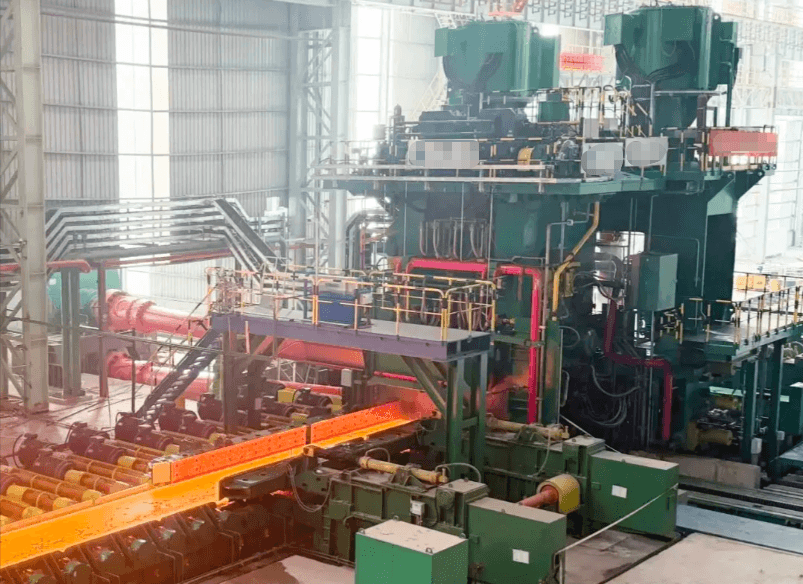
In the extreme operating environments of hot-rolling lines—characterized by high temperatures, high humidity, intense vibration, and conductive dust contamination—PCBA protection strategies directly determine the reliability of on-site instrumentation and control systems as well as production line uptime. With the triple advantages of nanoscale thickness, a flexible molecular structure, and a superhydrophobic interface, the Fluere™ series of nano-coatings offers a field-proven, effective solution to these industry challenges.
I. The "Electronics Killer" on the Hot Rolling Line: Cooling Water Is More Than Just Water
In July 2025, during routine maintenance of a 1780mm hot strip rolling line in North China, a hydraulic AGC (Automatic Gauge Control) displacement sensor near the F4 finishing mill stand experienced intermittent signal loss. Upon dismantling the sensor's internal signal conditioning PCBA (Printed Circuit Board Assembly), technicians discovered extensive green corrosion across the board's surface, with four circuit traces completely severed. This failure occurred just 11 months after the sensor had last been replaced.
This is not an isolated incident. For the hundreds of field sensors and actuators distributed around the mill stands, roller tables, and cooling sections of the hot rolling line, the service life of their internal electronic modules is typically only one-third to one-half of their design life. The culprit is the ubiquitous cooling water—and the chain reactions it triggers.
1.1 Direct Spray and Splash: A "Shower" for the PCBA
Cooling water on the hot rolling line operates at pressures of 0.8–1.5 MPa, with nozzle flow rates reaching hundreds of liters per minute. Upon striking steel billets and rolls heated to 700–1200°C, the water instantly vaporizes; the mixture of high-pressure steam and liquid droplets creates a dense mist that envelops the area within a 5–10 meter radius of the mill stand. Equipment casings in this zone are subjected to kilograms of mist accumulation every hour.
Although sensor and actuator housings may be rated IP65 or even IP67, actual field conditions are far harsher than those in a laboratory. Sealing rings age prematurely due to thermal radiation (60–80°C), cable glands loosen from vibration, and housing seams develop microscopic gaps caused by temperature fluctuations. Water molecules penetrate through these gaps and become trapped within the sealed enclosure, subjecting the PCBA to a relentless cycle of "soaking and baking."
1.2 Steam Condensation and High-Temperature Baking: A 60–80°C Hot-and-Humid Cycle
A threat even more insidious than direct splashing is steam condensation. The relative humidity of the air surrounding the rolling mill consistently remains above 95%. Due to internal circuit self-heating and external thermal radiation, the surface temperature of the equipment's PCBA often reaches 60–80°C. When the rolling line pauses briefly and the temperature inside the housing drops, residual water vapor condenses into a liquid water film on the PCBA surface. This "heat-humidity-cooling-condensation" cycle occurs multiple times daily, causing far more damage to the circuit board than continuous immersion.
Field measurements taken on a displacement sensor PCBA at the F7 finishing mill of a steel plant in southern China showed that the board surface temperature ranged from 68°C to 73°C during normal operation. After the machine stopped and cooled down, visible water droplets appeared on the board, and the insulation resistance plummeted from the normal level of 10¹² Ω to below 10⁵ Ω. A drop in insulation of this magnitude is sufficient to completely drown out millivolt-level sensor signals amidst the noise of leakage current.
1.3 Iron Oxide Dust: An Invisible Conductive Bridge
During hot rolling, iron oxide scale (Fe₃O₄/Fe₂O₃) flakes off the steel billet surface, creating dust particles ranging from 5 to 50 μm in size that—carried by cooling water mist—penetrate even the smallest gaps. These iron oxides are somewhat conductive (with a resistivity of approximately 10⁻³–10⁻¹ Ω·m). When they deposit on the PCBA surface and mix with condensed water, they form hundreds of micro-conductive paths between adjacent solder pads and component pins.
Even more problematic is that, under the influence of a DC electric field, the iron oxide dust undergoes electrochemical migration, forming dendritic deposits. Failure analysis has repeatedly revealed iron oxide dendrites growing between the adjacent pins of QFP-packaged chips; the resistance between pins spaced 0.5 mm apart dropped to just a few hundred ohms, directly causing circuit logic errors.
II. Vibration Fatigue: Why Conventional Conformal Coatings Fail Near Rolling Mills
If moisture and dust represent a "chemical attack" on the PCBA, then the vibration of the rolling mill constitutes a relentless "physical attack." The rolling force of a hot rolling mill can reach thousands of tons; the impact forces generated when the roll assembly bites and releases the steel are transmitted through the mill stand and foundation to all auxiliary equipment, creating broadband vibrations in the 10–50 Hz range with peak accelerations of 3–8 g.
2.1 Impact of sustained 10–50 Hz vibration on coating adhesion
Traditional acrylic or polyurethane conformal coatings form rigid or semi-rigid films with thicknesses of 50–200 μm. While they provide good protection under static laboratory conditions, issues arise when subjected to rolling mill vibrations:
Differences in the Coefficient of Thermal Expansion (CTE) between the relatively thick coating and the PCB substrate (FR-4, CTE ≈ 14 ppm/°C) or components (epoxy resin, CTE ≈ 8–12 ppm/°C) generate interfacial shear stress during temperature cycling. Vibration amplifies this stress, leading to micro-cracking and delamination between the coating and the substrate. Rigid coatings cannot accommodate the micro-deformations of the PCB during vibration (FR-4 exhibits a deflection of 0.5–1 mm at 8 g acceleration), causing cracks to form at stress concentration points such as component lead roots and solder joint edges. Once the coating cracks, moisture-laden air infiltrates the fissures, triggering a "capillary condensation" effect where the humidity inside the crack becomes higher than the ambient humidity.
2.2 Comparative measurement: Vibration test data for acrylic conformal coating vs. nano-coating
We conducted accelerated life testing in the laboratory based on the typical vibration spectrum of a hot rolling line. Test conditions included a 10–50 Hz frequency sweep, 5 g RMS acceleration, 65°C temperature, and 90% RH humidity, with a 24-hour cycle (8 hours of vibration followed by 16 hours of rest). The test samples consisted of FR-4 boards with identical layouts, coated with either 100 μm of acrylic conformal coating or 5 μm of Fluere™ series nano-coating (10 samples per group). Significant differences emerged starting on Day 14: in the acrylic conformal coating group, eight units showed a drop in insulation resistance (to <10⁸ Ω), and over 60% exhibited coating cracks at the pin bases of the QFP-64 packages; conversely, all ten units in the nano-coating group maintained insulation resistance above 10¹¹ Ω with no visible cracks. By Day 28, all units in the conformal coating group had failed, whereas nine units in the nano-coating group remained functional. SEM cross-sectional analysis revealed that the nano-coating, due to its nanoscale thickness and flexible molecular structure, expands and contracts in sync with PCB micro-deformations, thereby avoiding stress concentration.
III. Sensor PCBA Protection: Field Case Studies Ranging from Temperature Probes to Displacement Sensors
3.1 Roughing Mill Exit Temperature Sensor: A Record of 24V Power Module Corrosion
The temperature sensor at the exit of the R2 roughing mill is installed approximately 1.5 meters above the roller table to measure the temperature of the intermediate slab (approx. 1050°C). The sensor's internal transmitter module contains a PCBA comprising a 24V DC-DC power supply, cold-junction compensation for the thermocouple, and a 4–20 mA output circuit, all housed within an IP65-rated aluminum casing. In 2024, the sensor at this location required replacement four times annually; each replacement incurred a direct cost of approximately 8,000 RMB, with associated downtime losses exceeding 200,000 RMB.
Disassembly of the failed modules revealed typical electrochemical corrosion at the solder pads of the TVS diode on the 24V power input line: the positive pad underwent anodic dissolution due to the combined effects of humidity and the 24V bias voltage, resulting in the complete disappearance of the copper foil and leaving behind blue-green copper salt deposits. Tin whiskers—slender single-crystal tin filaments—were also observed growing from the solder joint surfaces; the longest reached approximately 200 μm, nearly touching the adjacent grounding copper plane. Under conditions of high temperature, high humidity, and vibration, such tin whiskers pose a high risk of triggering instantaneous short circuits.
Following the application of Fluere™ S8 nano-coating (8% solids content, resulting in a dry film thickness of approx. 5 μm), the sensor at this location has operated continuously for 14 months without failure. The coating effectively blocks direct contact between water molecules and the pad metal, thereby severing the ionic pathways for electrochemical corrosion.
3.2 Hydraulic AGC Displacement Sensor: The Root Cause of Signal Drift
The hydraulic cylinder for AGC (Automatic Gauge Control) features a built-in magnetostrictive displacement sensor. Its detection head contains precision pulse generation and echo detection circuitry, outputting either a 0–10V signal or an SSI digital signal with a required resolution of 1 μm. Installed within the hydraulic cylinder's end cap—merely tens of centimeters from the roll bearing housing—the sensor is subjected to severe cooling water spray and intense vibration.
The fault was highly insidious: during normal rolling operations, the thickness deviation gradually increased, yet the AGC system reported no error. Post-incident analysis revealed that moisture contamination at the inverting input of an operational amplifier (op-amp) on the PCBA caused a leakage current of approximately 200 nA. This generated a 20 mV bias drift across the 100 kΩ feedback resistor, corresponding to a displacement measurement error of about 40 μm. For hot-rolled strip steel with a target thickness of 2.0 mm, a 40 μm error is sufficient to reduce the thickness accuracy rate by more than 3 percentage points. Following nano-coating treatment, the insulation resistance between the op-amp input pins stabilized above 10¹² Ω, leakage current dropped to the picoampere (pA) level, and the signal drift issue was completely eliminated.
IV. Actuator PCBA Protection: Safeguarding the Heart of Hydraulic and Pneumatic Valve Positioners
4.1 Servo Valve Amplifier PCBA: Humidity Sensitivity of ±15V Analog Circuits
Hot rolling line hydraulic servo systems extensively utilize electro-hydraulic servo valves from brands such as MOOG and Rexroth. The associated servo amplifier modules convert the controller's ±10V command signals into current signals (ranging from ±20 mA to ±100 mA) to drive the servo valve coils. The op-amps, power transistors, and precision resistor networks on the amplifier PCBA are extremely sensitive to humidity. At a hot rolling mill, the servo valve amplifier for the finishing mill's roll-bending system frequently triggered overcurrent alarms. Although the unit tested normally in the laboratory after replacement, the fault recurred upon reinstallation on-site. The root cause was identified as leakage current between the gate pins of the power-stage MOSFETs—induced by moisture—which triggered the overcurrent protection circuit. While the theoretical gate input impedance is in the order of 10¹² Ω, it dropped below 10⁶ Ω when covered by a condensation film; consequently, minute gate voltage drifts were amplified by the power stage into significant current deviations. After applying a nano-coating, the voltage across the gate protection resistor stabilized, and the rate of false overcurrent alarms dropped from over ten incidents per month to zero.
4.2 Pneumatic Valve Positioners: 4–20 mA Loop Leakage Current Issues
Pneumatic diaphragm control valves are widely used in the cooling water sections of hot rolling lines, with their valve positioners receiving 4–20 mA control signals from the DCS. The internal PCBA of the positioner houses I/V conversion circuits, position feedback processing circuits, and piezoelectric valve drive circuits. When the PCBA surface becomes damp, leakage current to the ground occurs at high-impedance nodes within the 4–20 mA input loop, causing deviations from the setpoint.
In one observed case, a cooling water control valve positioner exhibited actual opening fluctuations ranging from 42% to 58% despite a setpoint of 50%. Disassembly revealed a surface insulation resistance of only 3.2 MΩ, whereas the normal value should exceed 500 MΩ. Although the positioner's IP65-rated housing remained intact, moisture vapor had entered through gaps in the cable armor, causing repeated condensation on the PCBA surface due to diurnal temperature fluctuations. Following the application of a protective nano-coating and sealing of the cable entry point, loop control accuracy was restored to within ±1%.
V. Fluere™ Series Nano-Coatings: Specialized Protection Solutions for Hot Rolling Environments
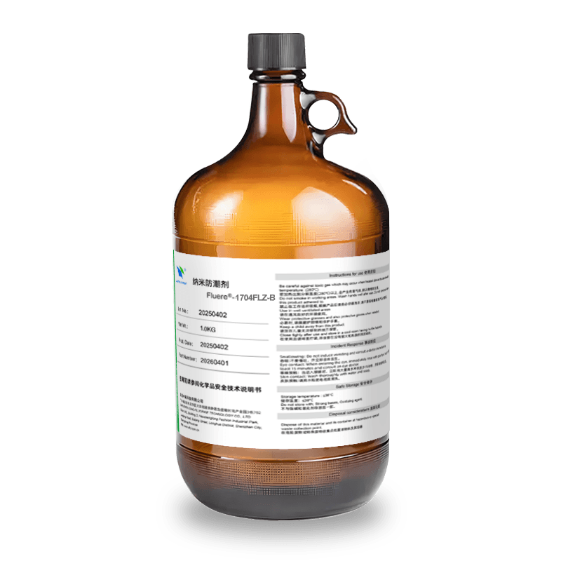
To address the need for protecting industrial electronics in extremely humid environments, Shenzhen Zhongfu has developed the Fluere series of nano-protective coating agents. This series utilizes an organic-inorganic hybrid nanomaterial system to form a dense, hydrophobic film (3–5 μm thick) on the PCBA surface via a dip-coating process.
5.1 Why Nanocoatings Are Better Suited Than Traditional Conformal Coatings for Hot-Running Environments
We compare them across four dimensions:
Thickness and Heat Dissipation: Traditional conformal coatings have a dry film thickness of 50–200 μm, resulting in significant thermal resistance; in 60–80°C environments, the PCBA junction temperature rises by an additional 5–15°C. In contrast, nanocoatings are only 3–5 μm thick, with a thermal resistance increase of less than 0.1°C/W, having virtually no impact on heat dissipation.
Flexibility and Vibration Resistance: Nanocoatings feature an organic-inorganic hybrid network structure with an elongation at break exceeding 50%. They can accommodate the micro-deformations caused by PCB vibration without cracking at component bases, unlike rigid coatings.
Protection Mechanism: Nanocoatings create a superhydrophobic interface on the PCBA surface with a contact angle exceeding 110°, preventing liquid water from spreading into a continuous film. Their dense, nanoscale structure significantly extends the permeation path for water vapor, resulting in a moisture permeability rate one to two orders of magnitude lower than that of traditional coatings.
Defect Tolerance: Due to high viscosity and thickness, traditional conformal coatings are prone to bubble formation and bridging between component leads. Nanocoatings, with their ultra-low viscosity and nanoscale thickness, can fully penetrate beneath fine-pitch packages—such as QFP and BGA—ensuring complete coverage without blind spots.
5.2 Fluere Series Selection Guide and Process Compatibility
| Model | Solids content | Recommended dry film thickness | Applicable PCBA types | Key performance characteristics | Suitability for hot-rolling environments |
|---|---|---|---|---|---|
| Fluere™ 01 | 1% | 0.1-0.5μm | High-density fine-pitch boards, RF circuits | Ultra-thin and lightweight; low dielectric constant | ★★☆☆☆ |
| Fluere™ 02 | 2% | 1-2μm | General-purpose sensor modules, signal conditioning boards | Balances protection and heat dissipation | ★★★☆☆ |
| Fluere™ 04 | 4% | 2-3μm | Valve positioner and transmitter PCBAs | Hydrophobic contact angle >105°; withstands 72 hours of salt spray | ★★★★☆ |
| Fluere™ 05 | 5% | 3-4μm | Hydraulic servo amplifiers, high-power modules | Withstands 500 cycles of damp-heat testing | ★★★★☆ |
| Fluere™ 08 | 8% | 4-5μm | Rolling mill core sensors, AGC displacement sensors | Hydrophobic contact angle >110°; vibration resistance (50 Hz/8g) | ★★★★★ |
| Fluere™ 10 | 10% | 5-8μm | Actuator PCBAs for extremely humid environments | Ultra-high density; withstands 168 hours of salt spray | ★★★★★ |
| Fluere™ 20 | 20% | 8-13μm | High-power rectifier/inverter module PCBAs | Thickest nano-film; provides both moisture resistance and insulation | ★★★☆☆ |
Recommended solutions for hot rolling lines: For core sensor and actuator PCBAs located within 5 meters of the rolling mill itself, Fluere 08 or 10 is recommended; for peripheral transmitters and positioners along the roller table, Fluere 04 or 05 is sufficient. All models feature eco-friendly, zero-VOC formulations; they require only a 3-second immersion for coating and cure in 3 minutes at room temperature, meeting the demands of fast-paced production line maintenance.
VI. Deployment and Performance of Dip-Coating Nano-Coatings in Hot Rolling Operations
6.1 On-site Implementation Process
Unlike traditional conformal coatings—which require spraying equipment, oven curing, and masking steps—the Fluere™ dip-coating process is extremely streamlined for on-site hot rolling line application:
Step 1: Remove the PCBA from its housing, clean surface flux residues and corrosion products using a specialized cleaner, and dry at 60°C for 10 minutes. Step 2: Fully immerse the PCBA in the Fluere series coating solution for 3 seconds and withdraw it at a steady speed (recommended withdrawal speed: 5–10 mm/s). Step 3: Allow to cure at room temperature for 3 minutes before reassembly. A single operator can complete the process in under 20 minutes without specialized equipment, making it highly practical for the tight 8–12 hour scheduled maintenance windows typical of hot rolling lines.
6.2 Summary of Operational Data
The following data covers the period from Q3 2024 to Q1 2026 for a 1780mm hot strip rolling line, tracking 47 sensor/actuator PCBAs in the finishing and roughing mill areas after the application of nano-coating protection:
Regarding failure rates: In the 12 months prior to implementation, there were 23 electronic failures involving sensors and actuators (an average of 1.92 per month); in the 18 months following implementation, there were only 4 such failures (all mechanical in nature and unrelated to the PCBAs), with the electronic failure rate dropping to zero. Annual maintenance costs decreased from approximately 186,000 RMB to 21,000 RMB. Unplanned downtime caused by electronic failures has been reduced from an annual average of 37 hours to zero; based on an estimated loss of approximately 80,000 RMB per hour of downtime, this measure alone yields annualized savings of nearly 3 million RMB.
For further details on the core principles of nano-coating moisture-proofing technology, please refer to the "In-Depth Guide to Nano-Coating Moisture-Proofing Technology"; for a comprehensive comparison of electronic protection materials, please consult the "PCBA Conformal Coating Selection Guide."
In the extreme operating environments of hot rolling lines—characterized by high temperatures, high humidity, intense vibration, and conductive dust contamination—the PCBA protection strategy directly determines the reliability of on-site instrumentation and control systems as well as the production line's uptime. Leveraging the triple advantages of nanoscale thickness, a flexible molecular structure, and a superhydrophobic interface, the Fluere™ series of nano-coatings offers a field-proven solution to these critical industry challenges.
In the extreme operating environments of hot-rolling lines—characterized by high temperatures, high humidity, intense vibration, and conductive dust contamination—PCBA protection strategies directly determine the reliability of on-site instrumentation and control systems as well as production line uptime. With the triple advantages of nanoscale thickness, a flexible molecular structure, and a superhydrophobic interface, the Fluere™ series of nano-coatings offers a field-proven, effective solution to these industry challenges.
I. The "Electronics Killer" on the Hot Rolling Line: Cooling Water Is More Than Just Water
In July 2025, during routine maintenance of a 1780mm hot strip rolling line in North China, a hydraulic AGC (Automatic Gauge Control) displacement sensor near the F4 finishing mill stand experienced intermittent signal loss. Upon dismantling the sensor's internal signal conditioning PCBA (Printed Circuit Board Assembly), technicians discovered extensive green corrosion across the board's surface, with four circuit traces completely severed. This failure occurred just 11 months after the sensor had last been replaced.
This is not an isolated incident. For the hundreds of field sensors and actuators distributed around the mill stands, roller tables, and cooling sections of the hot rolling line, the service life of their internal electronic modules is typically only one-third to one-half of their design life. The culprit is the ubiquitous cooling water—and the chain reactions it triggers.
1.1 Direct Spray and Splash: A "Shower" for the PCBA
Cooling water on the hot rolling line operates at pressures of 0.8–1.5 MPa, with nozzle flow rates reaching hundreds of liters per minute. Upon striking steel billets and rolls heated to 700–1200°C, the water instantly vaporizes; the mixture of high-pressure steam and liquid droplets creates a dense mist that envelops the area within a 5–10 meter radius of the mill stand. Equipment casings in this zone are subjected to kilograms of mist accumulation every hour.
Although sensor and actuator housings may be rated IP65 or even IP67, actual field conditions are far harsher than those in a laboratory. Sealing rings age prematurely due to thermal radiation (60–80°C), cable glands loosen from vibration, and housing seams develop microscopic gaps caused by temperature fluctuations. Water molecules penetrate through these gaps and become trapped within the sealed enclosure, subjecting the PCBA to a relentless cycle of "soaking and baking."
1.2 Steam Condensation and High-Temperature Baking: A 60–80°C Hot-and-Humid Cycle
A threat even more insidious than direct splashing is steam condensation. The relative humidity of the air surrounding the rolling mill consistently remains above 95%. Due to internal circuit self-heating and external thermal radiation, the surface temperature of the equipment's PCBA often reaches 60–80°C. When the rolling line pauses briefly and the temperature inside the housing drops, residual water vapor condenses into a liquid water film on the PCBA surface. This "heat-humidity-cooling-condensation" cycle occurs multiple times daily, causing far more damage to the circuit board than continuous immersion.
Field measurements taken on a displacement sensor PCBA at the F7 finishing mill of a steel plant in southern China showed that the board surface temperature ranged from 68°C to 73°C during normal operation. After the machine stopped and cooled down, visible water droplets appeared on the board, and the insulation resistance plummeted from the normal level of 10¹² Ω to below 10⁵ Ω. A drop in insulation of this magnitude is sufficient to completely drown out millivolt-level sensor signals amidst the noise of leakage current.
1.3 Iron Oxide Dust: An Invisible Conductive Bridge
During hot rolling, iron oxide scale (Fe₃O₄/Fe₂O₃) flakes off the steel billet surface, creating dust particles ranging from 5 to 50 μm in size that—carried by cooling water mist—penetrate even the smallest gaps. These iron oxides are somewhat conductive (with a resistivity of approximately 10⁻³–10⁻¹ Ω·m). When they deposit on the PCBA surface and mix with condensed water, they form hundreds of micro-conductive paths between adjacent solder pads and component pins.
Even more problematic is that, under the influence of a DC electric field, the iron oxide dust undergoes electrochemical migration, forming dendritic deposits. Failure analysis has repeatedly revealed iron oxide dendrites growing between the adjacent pins of QFP-packaged chips; the resistance between pins spaced 0.5 mm apart dropped to just a few hundred ohms, directly causing circuit logic errors.
II. Vibration Fatigue: Why Conventional Conformal Coatings Fail Near Rolling Mills
If moisture and dust represent a "chemical attack" on the PCBA, then the vibration of the rolling mill constitutes a relentless "physical attack." The rolling force of a hot rolling mill can reach thousands of tons; the impact forces generated when the roll assembly bites and releases the steel are transmitted through the mill stand and foundation to all auxiliary equipment, creating broadband vibrations in the 10–50 Hz range with peak accelerations of 3–8 g.
2.1 Impact of sustained 10–50 Hz vibration on coating adhesion
Traditional acrylic or polyurethane conformal coatings form rigid or semi-rigid films with thicknesses of 50–200 μm. While they provide good protection under static laboratory conditions, issues arise when subjected to rolling mill vibrations:
Differences in the Coefficient of Thermal Expansion (CTE) between the relatively thick coating and the PCB substrate (FR-4, CTE ≈ 14 ppm/°C) or components (epoxy resin, CTE ≈ 8–12 ppm/°C) generate interfacial shear stress during temperature cycling. Vibration amplifies this stress, leading to micro-cracking and delamination between the coating and the substrate. Rigid coatings cannot accommodate the micro-deformations of the PCB during vibration (FR-4 exhibits a deflection of 0.5–1 mm at 8 g acceleration), causing cracks to form at stress concentration points such as component lead roots and solder joint edges. Once the coating cracks, moisture-laden air infiltrates the fissures, triggering a "capillary condensation" effect where the humidity inside the crack becomes higher than the ambient humidity.
2.2 Comparative measurement: Vibration test data for acrylic conformal coating vs. nano-coating
We conducted accelerated life testing in the laboratory based on the typical vibration spectrum of a hot rolling line. Test conditions included a 10–50 Hz frequency sweep, 5 g RMS acceleration, 65°C temperature, and 90% RH humidity, with a 24-hour cycle (8 hours of vibration followed by 16 hours of rest). The test samples consisted of FR-4 boards with identical layouts, coated with either 100 μm of acrylic conformal coating or 5 μm of Fluere™ series nano-coating (10 samples per group). Significant differences emerged starting on Day 14: in the acrylic conformal coating group, eight units showed a drop in insulation resistance (to <10⁸ Ω), and over 60% exhibited coating cracks at the pin bases of the QFP-64 packages; conversely, all ten units in the nano-coating group maintained insulation resistance above 10¹¹ Ω with no visible cracks. By Day 28, all units in the conformal coating group had failed, whereas nine units in the nano-coating group remained functional. SEM cross-sectional analysis revealed that the nano-coating, due to its nanoscale thickness and flexible molecular structure, expands and contracts in sync with PCB micro-deformations, thereby avoiding stress concentration.
III. Sensor PCBA Protection: Field Case Studies Ranging from Temperature Probes to Displacement Sensors
3.1 Roughing Mill Exit Temperature Sensor: A Record of 24V Power Module Corrosion
The temperature sensor at the exit of the R2 roughing mill is installed approximately 1.5 meters above the roller table to measure the temperature of the intermediate slab (approx. 1050°C). The sensor's internal transmitter module contains a PCBA comprising a 24V DC-DC power supply, cold-junction compensation for the thermocouple, and a 4–20 mA output circuit, all housed within an IP65-rated aluminum casing. In 2024, the sensor at this location required replacement four times annually; each replacement incurred a direct cost of approximately 8,000 RMB, with associated downtime losses exceeding 200,000 RMB.
Disassembly of the failed modules revealed typical electrochemical corrosion at the solder pads of the TVS diode on the 24V power input line: the positive pad underwent anodic dissolution due to the combined effects of humidity and the 24V bias voltage, resulting in the complete disappearance of the copper foil and leaving behind blue-green copper salt deposits. Tin whiskers—slender single-crystal tin filaments—were also observed growing from the solder joint surfaces; the longest reached approximately 200 μm, nearly touching the adjacent grounding copper plane. Under conditions of high temperature, high humidity, and vibration, such tin whiskers pose a high risk of triggering instantaneous short circuits.
Following the application of Fluere™ S8 nano-coating (8% solids content, resulting in a dry film thickness of approx. 5 μm), the sensor at this location has operated continuously for 14 months without failure. The coating effectively blocks direct contact between water molecules and the pad metal, thereby severing the ionic pathways for electrochemical corrosion.
3.2 Hydraulic AGC Displacement Sensor: The Root Cause of Signal Drift
The hydraulic cylinder for AGC (Automatic Gauge Control) features a built-in magnetostrictive displacement sensor. Its detection head contains precision pulse generation and echo detection circuitry, outputting either a 0–10V signal or an SSI digital signal with a required resolution of 1 μm. Installed within the hydraulic cylinder's end cap—merely tens of centimeters from the roll bearing housing—the sensor is subjected to severe cooling water spray and intense vibration.
The fault was highly insidious: during normal rolling operations, the thickness deviation gradually increased, yet the AGC system reported no error. Post-incident analysis revealed that moisture contamination at the inverting input of an operational amplifier (op-amp) on the PCBA caused a leakage current of approximately 200 nA. This generated a 20 mV bias drift across the 100 kΩ feedback resistor, corresponding to a displacement measurement error of about 40 μm. For hot-rolled strip steel with a target thickness of 2.0 mm, a 40 μm error is sufficient to reduce the thickness accuracy rate by more than 3 percentage points. Following nano-coating treatment, the insulation resistance between the op-amp input pins stabilized above 10¹² Ω, leakage current dropped to the picoampere (pA) level, and the signal drift issue was completely eliminated.
IV. Actuator PCBA Protection: Safeguarding the Heart of Hydraulic and Pneumatic Valve Positioners
4.1 Servo Valve Amplifier PCBA: Humidity Sensitivity of ±15V Analog Circuits
Hot rolling line hydraulic servo systems extensively utilize electro-hydraulic servo valves from brands such as MOOG and Rexroth. The associated servo amplifier modules convert the controller's ±10V command signals into current signals (ranging from ±20 mA to ±100 mA) to drive the servo valve coils. The op-amps, power transistors, and precision resistor networks on the amplifier PCBA are extremely sensitive to humidity. At a hot rolling mill, the servo valve amplifier for the finishing mill's roll-bending system frequently triggered overcurrent alarms. Although the unit tested normally in the laboratory after replacement, the fault recurred upon reinstallation on-site. The root cause was identified as leakage current between the gate pins of the power-stage MOSFETs—induced by moisture—which triggered the overcurrent protection circuit. While the theoretical gate input impedance is in the order of 10¹² Ω, it dropped below 10⁶ Ω when covered by a condensation film; consequently, minute gate voltage drifts were amplified by the power stage into significant current deviations. After applying a nano-coating, the voltage across the gate protection resistor stabilized, and the rate of false overcurrent alarms dropped from over ten incidents per month to zero.
4.2 Pneumatic Valve Positioners: 4–20 mA Loop Leakage Current Issues
Pneumatic diaphragm control valves are widely used in the cooling water sections of hot rolling lines, with their valve positioners receiving 4–20 mA control signals from the DCS. The internal PCBA of the positioner houses I/V conversion circuits, position feedback processing circuits, and piezoelectric valve drive circuits. When the PCBA surface becomes damp, leakage current to the ground occurs at high-impedance nodes within the 4–20 mA input loop, causing deviations from the setpoint.
In one observed case, a cooling water control valve positioner exhibited actual opening fluctuations ranging from 42% to 58% despite a setpoint of 50%. Disassembly revealed a surface insulation resistance of only 3.2 MΩ, whereas the normal value should exceed 500 MΩ. Although the positioner's IP65-rated housing remained intact, moisture vapor had entered through gaps in the cable armor, causing repeated condensation on the PCBA surface due to diurnal temperature fluctuations. Following the application of a protective nano-coating and sealing of the cable entry point, loop control accuracy was restored to within ±1%.
V. Fluere™ Series Nano-Coatings: Specialized Protection Solutions for Hot Rolling Environments
To address the need for protecting industrial electronics in extremely humid environments, Shenzhen Zhongfu has developed the Fluere series of nano-protective coating agents. This series utilizes an organic-inorganic hybrid nanomaterial system to form a dense, hydrophobic film (3–5 μm thick) on the PCBA surface via a dip-coating process.
5.1 Why Nanocoatings Are Better Suited Than Traditional Conformal Coatings for Hot-Running Environments
We compare them across four dimensions:
Thickness and Heat Dissipation: Traditional conformal coatings have a dry film thickness of 50–200 μm, resulting in significant thermal resistance; in 60–80°C environments, the PCBA junction temperature rises by an additional 5–15°C. In contrast, nanocoatings are only 3–5 μm thick, with a thermal resistance increase of less than 0.1°C/W, having virtually no impact on heat dissipation.
Flexibility and Vibration Resistance: Nanocoatings feature an organic-inorganic hybrid network structure with an elongation at break exceeding 50%. They can accommodate the micro-deformations caused by PCB vibration without cracking at component bases, unlike rigid coatings.
Protection Mechanism: Nanocoatings create a superhydrophobic interface on the PCBA surface with a contact angle exceeding 110°, preventing liquid water from spreading into a continuous film. Their dense, nanoscale structure significantly extends the permeation path for water vapor, resulting in a moisture permeability rate one to two orders of magnitude lower than that of traditional coatings.
Defect Tolerance: Due to high viscosity and thickness, traditional conformal coatings are prone to bubble formation and bridging between component leads. Nanocoatings, with their ultra-low viscosity and nanoscale thickness, can fully penetrate beneath fine-pitch packages—such as QFP and BGA—ensuring complete coverage without blind spots.
5.2 Fluere Series Selection Guide and Process Compatibility
| Model | Solids content | Recommended dry film thickness | Applicable PCBA types | Key performance characteristics | Suitability for hot-rolling environments |
|---|---|---|---|---|---|
| Fluere™ 01 | 1% | 0.1-0.5μm | High-density fine-pitch boards, RF circuits | Ultra-thin and lightweight; low dielectric constant | ★★☆☆☆ |
| Fluere™ 02 | 2% | 1-2μm | General-purpose sensor modules, signal conditioning boards | Balances protection and heat dissipation | ★★★☆☆ |
| Fluere™ 04 | 4% | 2-3μm | Valve positioner and transmitter PCBAs | Hydrophobic contact angle >105°; withstands 72 hours of salt spray | ★★★★☆ |
| Fluere™ 05 | 5% | 3-4μm | Hydraulic servo amplifiers, high-power modules | Withstands 500 cycles of damp-heat testing | ★★★★☆ |
| Fluere™ 08 | 8% | 4-5μm | Rolling mill core sensors, AGC displacement sensors | Hydrophobic contact angle >110°; vibration resistance (50 Hz/8g) | ★★★★★ |
| Fluere™ 10 | 10% | 5-8μm | Actuator PCBAs for extremely humid environments | Ultra-high density; withstands 168 hours of salt spray | ★★★★★ |
| Fluere™ 20 | 20% | 8-13μm | High-power rectifier/inverter module PCBAs | Thickest nano-film; provides both moisture resistance and insulation | ★★★☆☆ |
Recommended solutions for hot rolling lines: For core sensor and actuator PCBAs located within 5 meters of the rolling mill itself, Fluere 08 or 10 is recommended; for peripheral transmitters and positioners along the roller table, Fluere 04 or 05 is sufficient. All models feature eco-friendly, zero-VOC formulations; they require only a 3-second immersion for coating and cure in 3 minutes at room temperature, meeting the demands of fast-paced production line maintenance.
VI. Deployment and Performance of Dip-Coating Nano-Coatings in Hot Rolling Operations
6.1 On-site Implementation Process
Unlike traditional conformal coatings—which require spraying equipment, oven curing, and masking steps—the Fluere™ dip-coating process is extremely streamlined for on-site hot rolling line application:
Step 1: Remove the PCBA from its housing, clean surface flux residues and corrosion products using a specialized cleaner, and dry at 60°C for 10 minutes. Step 2: Fully immerse the PCBA in the Fluere series coating solution for 3 seconds and withdraw it at a steady speed (recommended withdrawal speed: 5–10 mm/s). Step 3: Allow to cure at room temperature for 3 minutes before reassembly. A single operator can complete the process in under 20 minutes without specialized equipment, making it highly practical for the tight 8–12 hour scheduled maintenance windows typical of hot rolling lines.
6.2 Summary of Operational Data
The following data covers the period from Q3 2024 to Q1 2026 for a 1780mm hot strip rolling line, tracking 47 sensor/actuator PCBAs in the finishing and roughing mill areas after the application of nano-coating protection:
Regarding failure rates: In the 12 months prior to implementation, there were 23 electronic failures involving sensors and actuators (an average of 1.92 per month); in the 18 months following implementation, there were only 4 such failures (all mechanical in nature and unrelated to the PCBAs), with the electronic failure rate dropping to zero. Annual maintenance costs decreased from approximately 186,000 RMB to 21,000 RMB. Unplanned downtime caused by electronic failures has been reduced from an annual average of 37 hours to zero; based on an estimated loss of approximately 80,000 RMB per hour of downtime, this measure alone yields annualized savings of nearly 3 million RMB.
For further details on the core principles of nano-coating moisture-proofing technology, please refer to the "In-Depth Guide to Nano-Coating Moisture-Proofing Technology"; for a comprehensive comparison of electronic protection materials, please consult the "PCBA Conformal Coating Selection Guide."
In the extreme operating environments of hot rolling lines—characterized by high temperatures, high humidity, intense vibration, and conductive dust contamination—the PCBA protection strategy directly determines the reliability of on-site instrumentation and control systems as well as the production line's uptime. Leveraging the triple advantages of nanoscale thickness, a flexible molecular structure, and a superhydrophobic interface, the Fluere™ series of nano-coatings offers a field-proven solution to these critical industry challenges.