

You may have noticed a pattern: EV charging stations are most prone to breaking down during public holidays. During the May Day, National Day, and Spring Festival holidays, throngs of EV owners hit the highways, only to find that three out of four chargers at a rest stop are out of service for repairs. A look at the fault logs reveals that the culprit is almost always a "control board anomaly" or "communication module failure." Upon disassembly, the PCBA circuit boards are found riddled with corrosion—and the root cause comes down to a single word: moisture.
By the end of 2025, China’s inventory of public charging piles had surpassed 3.5 million units, with an annual growth rate exceeding 40%. Yet, few pay attention to another set of figures: operations and maintenance (O&M) data from charging operators reveals that the annual failure rate for outdoor charging pile control boards is as high as 8%–15%. Notably, PCBA corrosion and failure caused by moisture and condensation account for over 50% of these incidents. Replacing the PCBA control board of a 120kW DC fast-charging pile can easily cost thousands of yuan; when combined with revenue losses from downtime and the costs associated with user complaints, the average annual O&M cost per pile easily exceeds ten thousand yuan.
Just how difficult is it to protect the PCBA within a charging pile? Traditional methods rely on the brute-force approach of sealed cabinets, while emerging solutions utilize nano-coatings to address the issue at the circuit board level. Today, we will stage a "debate" to dissect these two approaches and determine which is truly better suited to the actual operating environment of charging pile control boards.
Round 1: What exactly threatens the charging pile PCBA?
Before the debate begins, we must identify the "opponent." Charging pile PCBAs face not just a single threat, but a combined assault from four environmental factors.
Condensation: The "Predawn Killer" of Charging Pile PCBAs
Charging pile cabinets are not hermetically sealed; ventilation is essential for heat dissipation. Under intense daytime sun, the internal cabinet temperature can soar above 60°C. As night falls and the external temperature plummets, water vapor inside the cabinet reaches its dew point, condensing into tiny droplets on the PCBA surface. A single condensation droplet just 0.3mm in diameter—landing precisely between two solder balls on a BGA chip—can trigger a catastrophe. Under a bias electric field of tens or even hundreds of volts, ions within the droplet migrate along the field lines, rapidly forming a conductive metal dendrite between adjacent pins within days. Once a short circuit occurs, critical components—such as the billing module, communication module, or even the main control chip—can be instantly destroyed.
Even more critical is the fact that condensation in charging piles is not merely an occasional occurrence. During the southern "plum rain" season and the northern autumn and winter months, condensation may form every early morning, evaporate after sunrise, and reappear the following morning. This recurring wet-dry cycle causes cumulative damage to the FR-4 PCBA substrate: micro-cracks gradually expand within the material, eventually leading to interlayer short circuits.
Salt Spray and Industrial Exhaust: "Gaseous Assassins" That Cabinets Can't Block
Many assume that simply housing a charging pile in an IP54 or IP65-rated cabinet solves all problems. However, IP ratings address only liquid water and solid particles; they are completely ineffective against corrosive gases. For charging piles in coastal cities, sodium chloride particles in salt spray penetrate vents as aerosols and dissolve into condensation droplets, creating a highly conductive electrolyte solution. Sulfur dioxide and nitrogen oxides in industrial zones act similarly—invisible and intangible, yet chemically destructive.
According to IPC-TM-650 testing standards, unprotected PCBAs exposed to a 5% salt spray environment for 72 hours exhibit visible white corrosion products on solder joint surfaces, with insulation resistance plummeting from the 10¹² Ω range to below 10¹⁰ Ω.
Thermal Cycling: "Chronic Fatigue" in Charging Pile PCBAs
Charging piles often experience daily temperature fluctuations exceeding 40°C during start-stop cycles. In summer, the combination of midday sun exposure and heat generated by high-power charging can push local PCBA temperatures above 85°C, whereas in deep winter, the unit may sit completely idle in sub-zero temperatures (below -10°C). Based on 365 thermal cycles per year, a five-year lifespan entails over 1,800 cycles of alternating heat and cold. With each cycle, the difference in the Coefficient of Thermal Expansion (CTE) between the PCB substrate (approx. 14 ppm/°C) and the solder (approx. 25 ppm/°C) generates microscopic stress. A cumulative total of 1,800 cycles is sufficient to cause fatigue cracks in solder joints or lead to the cracking and delamination of traditional conformal coatings applied to the PCBA surface.
Dust and Conductive Particles: Overlooked "Silent Killers"
Charging piles are mostly installed in open environments such as roadside areas and parking lots. Carbon particles from vehicle exhaust, rubber dust from tire wear, and cement dust from construction sites—these particulates enter the cabinet via airflow and settle on the PCBA surface. While dry, they are merely "dirt"; however, upon contact with condensation, the moistened dust transforms into a microscopic conductive network, further reducing the surface insulation resistance of the PCBA and accelerating electrochemical corrosion.
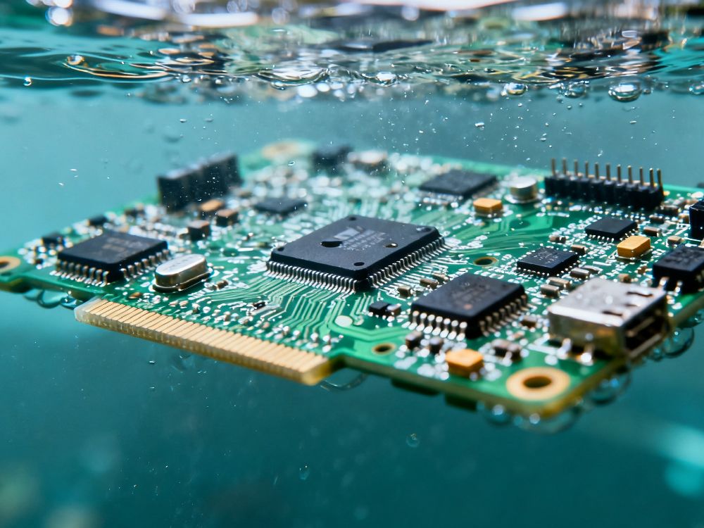
Figure 1: Immersion-type nano-coating process for EV charging station PCBA circuit boards.
Round 2: Can traditional protection methods hold up?
There are currently three mainstream PCBA protection strategies in the charging pile industry; let’s analyze how each performs in this specific application scenario.
Solution 1: Structural Sealing—"Keeps out rain, but not vapor"
IP54/IP65-rated cabinets serve as the first line of defense for charging pile PCBAs. While they effectively block rain, splashes, and dust, charging piles require heat dissipation and ventilation; wherever there are vents, condensation and corrosive gases can enter unimpeded. Even more problematic, the cabinet itself can exacerbate condensation: heat trapped inside during the day causes the cabinet walls to cool faster than the outside air at night, leading water vapor to condense preferentially on the cabinet walls and the PCBA surface.
Solution 2: Conformal Coating—"Cracked all over after five years"
Acrylic or polyurethane conformal coatings are currently the most widely used PCBA protection method. A 25–100μm layer covers the circuit board surface, theoretically isolating it from moisture. However, the charging pile environment—characterized by daily temperature fluctuations exceeding 40°C—is a nightmare for these coatings; repeated thermal expansion and contraction inevitably cause micro-cracks to form in the film. These cracks, often only a few micrometers wide and invisible to the naked eye, act as "highways" for water molecules and corrosive ions. Once moisture penetrates beneath the coating, the layer actually hinders evaporation, creating a "smoldering" type of corrosion—the exterior looks pristine, while the interior is completely rotted.
Solution 3: Potting—"Perfect protection, disastrous heat dissipation"
Encapsulating the entire PCBA in epoxy resin or polyurethane offers impeccable protection. However, a potting layer 2–10mm thick is a poor thermal conductor; for high-heat components like charging pile power modules, potting is essentially like wrapping the PCBA in a thick quilt. Addressing heat dissipation issues requires either throttling power or installing a larger heatsink—both of which compromise the charging station's cost-efficiency and performance. Furthermore, once the PCBA is encapsulated, it cannot be repaired; if a control board worth thousands of yuan malfunctions, the entire board must be replaced.
| Protection Method | Water and moisture resistance | Salt spray resistance | Thermal cycling resistance | Heat dissipation impact | Reworkability |
|---|---|---|---|---|---|
| IP54/IP65 Enclosures | Protects against liquid water only | Ineffective | No impact | Depends on airflow path design | — |
| Acrylic Conformal Coating | Initially effective | Average | Poor (micro-cracks) | Slight effect | Difficult |
| Polyurethane Potting | Excellent | Excellent | Excellent | Severely hinders | Non-reworkable |
| Nano-coating | Excellent | Excellent | Excellent | Thermal conductivity of 0.88; negligible impact | Repairable |
Round 3: Why are nano-coatings considered "better suited for charging piles"?
Unlike conformal coatings, which rely on "building up thickness," nano-coatings utilize a strategy of "densification and chemical bonding."
It’s not about "blocking water," but "leaving water nowhere to adhere."
Zhongfu Technology’s nano-moisture-proofing agent is based on a fluorine-modified polyester resin system. Fluorine atoms along the molecular chain impart extremely low surface energy to the coating, resulting in a water contact angle of 117–123° (per GB/T 30693 standards). When condensation droplets land on the nano-coated surface of a charging pile PCBA, they do not spread into a film; instead, they bead up into spheres that roll off under gravity or slight vibration. Even if residual droplets remain, the coating's dense molecular structure and chemical inertness prevent water molecules and corrosive ions from penetrating the PCB substrate.
Film thickness of just 0.1–13 μm: No compromise on heat dissipation, rework, or inspection.
With a dry film thickness of 0.1–13 μm, the nano-coating is 30 to 60 times thinner than traditional conformal coatings. At this micron-scale thickness, the coating's thermal conductivity (0.88 W/m·K) contributes negligibly to overall thermal resistance, ensuring that heat dissipation for the charging pile's power modules remains unaffected. Crucially, the coating is ultra-thin and transparent (99% light transmission); it does not obscure silkscreen markings or QR codes, nor does it interfere with AOI (Automated Optical Inspection). While the densely packed components and connectors on a charging pile PCBA require tedious manual masking when applying conformal coatings, nano-coatings are applied via a single-step immersion process for the entire board, eliminating the need for masking entirely. Data-backed performance: Over 1,000 hours in "Double 85" testing and no corrosion after 72 hours of salt spray exposure.
In "Double 85" damp-heat aging tests (85°C, 85% RH, powered operation, per GB/T 2423.50 standards), charging pile PCBAs treated with the nano-coating operated continuously for over 1,000 hours without significant degradation in insulation resistance. Under identical conditions, unprotected PCBAs exhibited a significant rise in leakage current after just 200–300 hours.
In salt spray tests (5% NaCl, 35°C, per GB/T 2423.17 standards), solder joints on nano-coated PCBAs showed no signs of corrosion after 72 hours. In contrast, PCBAs relying solely on IP54 cabinet protection developed white corrosion products on solder joints within 48 hours.
Volume resistivity is a key indicator of insulation performance for charging pile PCBAs. Following nano-coating treatment, volume resistivity reaches 4.6 × 10¹² Ω·cm (per ASTM D150 standards). Even under condensation conditions, the coating maintains electrical insulation and signal integrity between nodes on the PCBA surface. The measured dielectric strength is 1.0 kV/25.4 μm, fully accommodating the 400V–1000V DC bus voltages common in charging piles.
Round 4: How is the nano-coating implemented on the production line?
A primary concern for charging pile manufacturers is whether introducing the nano-coating requires modifying the production line or adding extra process steps.
The answer is virtually zero modification. The nano-coating utilizes an immersion process consisting of just three steps: immersing the PCBA in the coating bath for approximately 3 seconds, removing and draining it, and curing it at room or low temperature for 3–5 minutes. It requires no high-temperature baking and generates no VOC emissions (thanks to an eco-friendly, zero-VOC formula). The coating bath can be directly integrated into existing post-SMT assembly lines, occupying a footprint of less than 3 square meters. This process offers more than just a low barrier to entry; it establishes a comprehensive "equipment + consumables + service" model for continuous protection. The immersion production line represents a one-time investment to build protection capabilities; coating agents are supplied continuously to match the charging pile production pace; and process parameters are periodically optimized to ensure long-term consistency in protection performance. For charging pile manufacturers, PCBA protection evolves from a "buy-and-spray-it-yourself" approach to a model where the supplier continuously guarantees protection quality.
Round 5: The Economics of O&M—Hidden Costs Are the Costliest
Let’s crunch the numbers using a specific scenario. Assume a charging station has ten 120kW DC fast-charging piles with an average annual failure rate of 12%. Each failure takes an average of 4 hours to repair, during which time the pile is out of service. Each pile delivers an average of 80 kWh of charge per hour, with a service fee of 0.4 RMB/kWh.
Loss per failure for a single pile: 4 hours × 80 kWh × 0.4 RMB = 128 RMB in lost service fees. Adding the 300 RMB on-site service fee and the 1,500 RMB cost for PCBA spare parts, the total cost per failure is approximately 1,928 RMB. The annual failure cost for 10 piles is: 10 × 12% × 1,928 ≈ 23,000 RMB.
If the failure rate is reduced from 12% to 3% (a reasonable expectation), approximately 17,000 RMB can be saved annually. When factoring in the indirect losses—such as users switching to competing stations because a pile was broken—the investment in PCBA protection proves to be far more cost-effective than it initially appears.
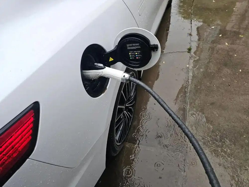
Figure 2: Immersion-based nano-coating process for EV charging station PCBA circuit boards.
As the EV charging pile industry matures, the focus of competition has shifted from simply "who can manufacture the units" to "whose units can operate reliably for five years without failure." With charging operators incorporating failure rates into tender specifications and EV owners "voting with their feet" by choosing stations that actually work well, PCBA protection is no longer a mere "nice-to-have" feature—it has become a critical factor determining product competitiveness.
This is not about replacing sealed enclosures or dismissing the value of conformal coatings. Rather, as charging piles expand from city centers to coastal highways and from temperate plains to high-altitude deserts, PCBA components require a more robust and enduring protection solution. Nanocoatings may well be the answer.
You may have noticed a pattern: EV charging stations are most prone to breaking down during public holidays. During the May Day, National Day, and Spring Festival holidays, throngs of EV owners hit the highways, only to find that three out of four chargers at a rest stop are out of service for repairs. A look at the fault logs reveals that the culprit is almost always a "control board anomaly" or "communication module failure." Upon disassembly, the PCBA circuit boards are found riddled with corrosion—and the root cause comes down to a single word: moisture.
By the end of 2025, China’s inventory of public charging piles had surpassed 3.5 million units, with an annual growth rate exceeding 40%. Yet, few pay attention to another set of figures: operations and maintenance (O&M) data from charging operators reveals that the annual failure rate for outdoor charging pile control boards is as high as 8%–15%. Notably, PCBA corrosion and failure caused by moisture and condensation account for over 50% of these incidents. Replacing the PCBA control board of a 120kW DC fast-charging pile can easily cost thousands of yuan; when combined with revenue losses from downtime and the costs associated with user complaints, the average annual O&M cost per pile easily exceeds ten thousand yuan.
Just how difficult is it to protect the PCBA within a charging pile? Traditional methods rely on the brute-force approach of sealed cabinets, while emerging solutions utilize nano-coatings to address the issue at the circuit board level. Today, we will stage a "debate" to dissect these two approaches and determine which is truly better suited to the actual operating environment of charging pile control boards.
Round 1: What exactly threatens the charging pile PCBA?
Before the debate begins, we must identify the "opponent." Charging pile PCBAs face not just a single threat, but a combined assault from four environmental factors.
Condensation: The "Predawn Killer" of Charging Pile PCBAs
Charging pile cabinets are not hermetically sealed; ventilation is essential for heat dissipation. Under intense daytime sun, the internal cabinet temperature can soar above 60°C. As night falls and the external temperature plummets, water vapor inside the cabinet reaches its dew point, condensing into tiny droplets on the PCBA surface. A single condensation droplet just 0.3mm in diameter—landing precisely between two solder balls on a BGA chip—can trigger a catastrophe. Under a bias electric field of tens or even hundreds of volts, ions within the droplet migrate along the field lines, rapidly forming a conductive metal dendrite between adjacent pins within days. Once a short circuit occurs, critical components—such as the billing module, communication module, or even the main control chip—can be instantly destroyed.
Even more critical is the fact that condensation in charging piles is not merely an occasional occurrence. During the southern "plum rain" season and the northern autumn and winter months, condensation may form every early morning, evaporate after sunrise, and reappear the following morning. This recurring wet-dry cycle causes cumulative damage to the FR-4 PCBA substrate: micro-cracks gradually expand within the material, eventually leading to interlayer short circuits.
Salt Spray and Industrial Exhaust: "Gaseous Assassins" That Cabinets Can't Block
Many assume that simply housing a charging pile in an IP54 or IP65-rated cabinet solves all problems. However, IP ratings address only liquid water and solid particles; they are completely ineffective against corrosive gases. For charging piles in coastal cities, sodium chloride particles in salt spray penetrate vents as aerosols and dissolve into condensation droplets, creating a highly conductive electrolyte solution. Sulfur dioxide and nitrogen oxides in industrial zones act similarly—invisible and intangible, yet chemically destructive.
According to IPC-TM-650 testing standards, unprotected PCBAs exposed to a 5% salt spray environment for 72 hours exhibit visible white corrosion products on solder joint surfaces, with insulation resistance plummeting from the 10¹² Ω range to below 10¹⁰ Ω.
Thermal Cycling: "Chronic Fatigue" in Charging Pile PCBAs
Charging piles often experience daily temperature fluctuations exceeding 40°C during start-stop cycles. In summer, the combination of midday sun exposure and heat generated by high-power charging can push local PCBA temperatures above 85°C, whereas in deep winter, the unit may sit completely idle in sub-zero temperatures (below -10°C). Based on 365 thermal cycles per year, a five-year lifespan entails over 1,800 cycles of alternating heat and cold. With each cycle, the difference in the Coefficient of Thermal Expansion (CTE) between the PCB substrate (approx. 14 ppm/°C) and the solder (approx. 25 ppm/°C) generates microscopic stress. A cumulative total of 1,800 cycles is sufficient to cause fatigue cracks in solder joints or lead to the cracking and delamination of traditional conformal coatings applied to the PCBA surface.
Dust and Conductive Particles: Overlooked "Silent Killers"
Charging piles are mostly installed in open environments such as roadside areas and parking lots. Carbon particles from vehicle exhaust, rubber dust from tire wear, and cement dust from construction sites—these particulates enter the cabinet via airflow and settle on the PCBA surface. While dry, they are merely "dirt"; however, upon contact with condensation, the moistened dust transforms into a microscopic conductive network, further reducing the surface insulation resistance of the PCBA and accelerating electrochemical corrosion.
Figure 1: Immersion-type nano-coating process for EV charging station PCBA circuit boards.
Round 2: Can traditional protection methods hold up?
There are currently three mainstream PCBA protection strategies in the charging pile industry; let’s analyze how each performs in this specific application scenario.
Solution 1: Structural Sealing—"Keeps out rain, but not vapor"
IP54/IP65-rated cabinets serve as the first line of defense for charging pile PCBAs. While they effectively block rain, splashes, and dust, charging piles require heat dissipation and ventilation; wherever there are vents, condensation and corrosive gases can enter unimpeded. Even more problematic, the cabinet itself can exacerbate condensation: heat trapped inside during the day causes the cabinet walls to cool faster than the outside air at night, leading water vapor to condense preferentially on the cabinet walls and the PCBA surface.
Solution 2: Conformal Coating—"Cracked all over after five years"
Acrylic or polyurethane conformal coatings are currently the most widely used PCBA protection method. A 25–100μm layer covers the circuit board surface, theoretically isolating it from moisture. However, the charging pile environment—characterized by daily temperature fluctuations exceeding 40°C—is a nightmare for these coatings; repeated thermal expansion and contraction inevitably cause micro-cracks to form in the film. These cracks, often only a few micrometers wide and invisible to the naked eye, act as "highways" for water molecules and corrosive ions. Once moisture penetrates beneath the coating, the layer actually hinders evaporation, creating a "smoldering" type of corrosion—the exterior looks pristine, while the interior is completely rotted.
Solution 3: Potting—"Perfect protection, disastrous heat dissipation"
Encapsulating the entire PCBA in epoxy resin or polyurethane offers impeccable protection. However, a potting layer 2–10mm thick is a poor thermal conductor; for high-heat components like charging pile power modules, potting is essentially like wrapping the PCBA in a thick quilt. Addressing heat dissipation issues requires either throttling power or installing a larger heatsink—both of which compromise the charging station's cost-efficiency and performance. Furthermore, once the PCBA is encapsulated, it cannot be repaired; if a control board worth thousands of yuan malfunctions, the entire board must be replaced.
| Protection Method | Water and moisture resistance | Salt spray resistance | Thermal cycling resistance | Heat dissipation impact | Reworkability |
|---|---|---|---|---|---|
| IP54/IP65 Enclosures | Protects against liquid water only | Ineffective | No impact | Depends on airflow path design | — |
| Acrylic Conformal Coating | Initially effective | Average | Poor (micro-cracks) | Slight effect | Difficult |
| Polyurethane Potting | Excellent | Excellent | Excellent | Severely hinders | Non-reworkable |
| Nano-coating | Excellent | Excellent | Excellent | Thermal conductivity of 0.88; negligible impact | Repairable |
Round 3: Why are nano-coatings considered "better suited for charging piles"?
Unlike conformal coatings, which rely on "building up thickness," nano-coatings utilize a strategy of "densification and chemical bonding."
It’s not about "blocking water," but "leaving water nowhere to adhere."
Zhongfu Technology’s nano-moisture-proofing agent is based on a fluorine-modified polyester resin system. Fluorine atoms along the molecular chain impart extremely low surface energy to the coating, resulting in a water contact angle of 117–123° (per GB/T 30693 standards). When condensation droplets land on the nano-coated surface of a charging pile PCBA, they do not spread into a film; instead, they bead up into spheres that roll off under gravity or slight vibration. Even if residual droplets remain, the coating's dense molecular structure and chemical inertness prevent water molecules and corrosive ions from penetrating the PCB substrate.
Film thickness of just 0.1–13 μm: No compromise on heat dissipation, rework, or inspection.
With a dry film thickness of 0.1–13 μm, the nano-coating is 30 to 60 times thinner than traditional conformal coatings. At this micron-scale thickness, the coating's thermal conductivity (0.88 W/m·K) contributes negligibly to overall thermal resistance, ensuring that heat dissipation for the charging pile's power modules remains unaffected. Crucially, the coating is ultra-thin and transparent (99% light transmission); it does not obscure silkscreen markings or QR codes, nor does it interfere with AOI (Automated Optical Inspection). While the densely packed components and connectors on a charging pile PCBA require tedious manual masking when applying conformal coatings, nano-coatings are applied via a single-step immersion process for the entire board, eliminating the need for masking entirely. Data-backed performance: Over 1,000 hours in "Double 85" testing and no corrosion after 72 hours of salt spray exposure.
In "Double 85" damp-heat aging tests (85°C, 85% RH, powered operation, per GB/T 2423.50 standards), charging pile PCBAs treated with the nano-coating operated continuously for over 1,000 hours without significant degradation in insulation resistance. Under identical conditions, unprotected PCBAs exhibited a significant rise in leakage current after just 200–300 hours.
In salt spray tests (5% NaCl, 35°C, per GB/T 2423.17 standards), solder joints on nano-coated PCBAs showed no signs of corrosion after 72 hours. In contrast, PCBAs relying solely on IP54 cabinet protection developed white corrosion products on solder joints within 48 hours.
Volume resistivity is a key indicator of insulation performance for charging pile PCBAs. Following nano-coating treatment, volume resistivity reaches 4.6 × 10¹² Ω·cm (per ASTM D150 standards). Even under condensation conditions, the coating maintains electrical insulation and signal integrity between nodes on the PCBA surface. The measured dielectric strength is 1.0 kV/25.4 μm, fully accommodating the 400V–1000V DC bus voltages common in charging piles.
Round 4: How is the nano-coating implemented on the production line?
A primary concern for charging pile manufacturers is whether introducing the nano-coating requires modifying the production line or adding extra process steps.
The answer is virtually zero modification. The nano-coating utilizes an immersion process consisting of just three steps: immersing the PCBA in the coating bath for approximately 3 seconds, removing and draining it, and curing it at room or low temperature for 3–5 minutes. It requires no high-temperature baking and generates no VOC emissions (thanks to an eco-friendly, zero-VOC formula). The coating bath can be directly integrated into existing post-SMT assembly lines, occupying a footprint of less than 3 square meters. This process offers more than just a low barrier to entry; it establishes a comprehensive "equipment + consumables + service" model for continuous protection. The immersion production line represents a one-time investment to build protection capabilities; coating agents are supplied continuously to match the charging pile production pace; and process parameters are periodically optimized to ensure long-term consistency in protection performance. For charging pile manufacturers, PCBA protection evolves from a "buy-and-spray-it-yourself" approach to a model where the supplier continuously guarantees protection quality.
Round 5: The Economics of O&M—Hidden Costs Are the Costliest
Let’s crunch the numbers using a specific scenario. Assume a charging station has ten 120kW DC fast-charging piles with an average annual failure rate of 12%. Each failure takes an average of 4 hours to repair, during which time the pile is out of service. Each pile delivers an average of 80 kWh of charge per hour, with a service fee of 0.4 RMB/kWh.
Loss per failure for a single pile: 4 hours × 80 kWh × 0.4 RMB = 128 RMB in lost service fees. Adding the 300 RMB on-site service fee and the 1,500 RMB cost for PCBA spare parts, the total cost per failure is approximately 1,928 RMB. The annual failure cost for 10 piles is: 10 × 12% × 1,928 ≈ 23,000 RMB.
If the failure rate is reduced from 12% to 3% (a reasonable expectation), approximately 17,000 RMB can be saved annually. When factoring in the indirect losses—such as users switching to competing stations because a pile was broken—the investment in PCBA protection proves to be far more cost-effective than it initially appears.
Figure 2: Immersion-based nano-coating process for EV charging station PCBA circuit boards.
As the EV charging pile industry matures, the focus of competition has shifted from simply "who can manufacture the units" to "whose units can operate reliably for five years without failure." With charging operators incorporating failure rates into tender specifications and EV owners "voting with their feet" by choosing stations that actually work well, PCBA protection is no longer a mere "nice-to-have" feature—it has become a critical factor determining product competitiveness.
This is not about replacing sealed enclosures or dismissing the value of conformal coatings. Rather, as charging piles expand from city centers to coastal highways and from temperate plains to high-altitude deserts, PCBA components require a more robust and enduring protection solution. Nanocoatings may well be the answer.